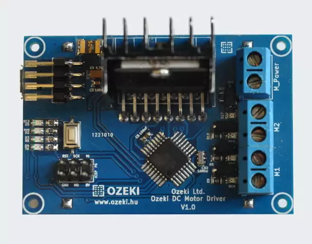
The is a modified Arduino Nano, that was built to drive upto 2 DC motors with the L298 motor driver. This is an open source board, with all the files needed for manufacturing. You may also freely modify the design.

The contains an ATmega328P microcontroller so you can program it just like an Arduino Nano using the Arduino IDE environment. It has a micro USB port, which is compatible with mobile phone USB cables. It is better then using an Arduino Nano, because it is more compact solution, since the RF modules are soldered directly to the board.


|
Download files for manufacturing
|
|
Datasheets
L298_H_Bridge.pdf
Tutorials
Examples
|
Specifications
- IC: ATmega328P
- Clock Speed: 16 MHz
- Flash Memory: 32 KB
- SRAM: 2 KB
- EEPROM: 1 KB
- USB support provided by a CH340G USB to serial chip:
- Micro USB (compatible with mobile phone USB cables)
- Connection to the Ozeki HUB Controller
- Power supply from USB (5V)
- 500mA resettable fuse
- Status LEDs: power, TX, RX, D13, D10
- Can be screwed on an Ozeki Matrix Board
- Product dimensions:
2.40in.[60.96mm]×0.80in.[20.32mm]
Pinout of the :

Wiring:
Connect the DC motors to the Ozeki DC Motor Driver as shown below.

Program codes
A code that controls 2 DC motors simultaneously
You can control two DC motors with this simple code. It controls both DC motors in the same way. The code start by slowly speeding up the motors until they reach the maximum speed and then they slow down and stop. At this point they suddenly reverse direction, slowly speed up and slow down again. This cycle continues infinitely until there is enough power resource to do it. In the video the left motor is stronger, but the right motor is faster.
The motor rotation stops when the digital value of the PWM signal goes below 50. We suggest
that you set this value for your own DC motors. You can find this value by smoothly lowering the value of the PWM signal.
e.g.:
analogWrite(EN_A, searched_value); // in our case at analogWrite(EN_A, 50); the motor is stopped
Downloadable code:
DCMotorDriverExampleCode.zip
Video 1 - How to move two DC motors in both directions

#define EN_A 9
#define EN_B 10

#define IN_1 14
#define IN_2 15
#define IN_3 16
#define IN_4 17

bool DIR=false;
int i=0;

bool Direction(bool DIR){
  if(DIR==false){
    digitalWrite(IN_1, HIGH);
    digitalWrite(IN_2, LOW);
    digitalWrite(IN_3, HIGH);
    digitalWrite(IN_4, LOW);
    DIR=true;
  } else {
    digitalWrite(IN_1, LOW);
    digitalWrite(IN_2, HIGH);
    digitalWrite(IN_3, LOW);
    digitalWrite(IN_4, HIGH);
    DIR=false;
  }
 return(DIR);
}

void setup(){
  pinMode(EN_A, OUTPUT);
  pinMode(EN_B, OUTPUT);
  pinMode(IN_1, OUTPUT);
  pinMode(IN_2, OUTPUT);
  pinMode(IN_3, OUTPUT);
  pinMode(IN_4, OUTPUT);
}

void loop() {
  DIR=Direction(DIR); //changes direction

  for(i=50;i<=255;i++){ //speeds up motors
    analogWrite(EN_A, i);
    analogWrite(EN_B, i);
    delay(50);
  }

  delay(5000);

  for(i=255;i>=50;i--){ //slows down motors
    if (i==50){
      i=0;
    }
    analogWrite(EN_A, i);
    analogWrite(EN_B, i);
    delay(50);
  }
  delay(5000);
}
Other modules
All of the Ozeki Processing Modules have ATmega328P or ATmega2560 microcontrollers integrated. Ozeki Modules can be connected to eachother like pieces of blocks. The connection is provided through USB to each module. They have M2 screw holes to give you an option to screw them on an Ozeki Matrix Board.
AutoConnect Link
If Ozeki 10 is running on your computer (such as on a Raspberry Pi) and you have plugged a microcontroller to it than Ozeki can be set to find serial devices on windows/linux and place them into a connection list so you can interact and control them through the software GUI.
