Modbus RTU/TCP gateway (Volison)
This is a multifunctional serial Modbus gateway, which integrates Modbus TCP, Modbus RTU and Modbus ASCII protocol. It can be used to seamlessly integrate Modbus Ethernet devices with Modbus serial devices. Using this guide, you can see how to wire the slaves to it, how to set up, and there is an example how use.

Connect the Modbus RTU/TCP gateway to PC
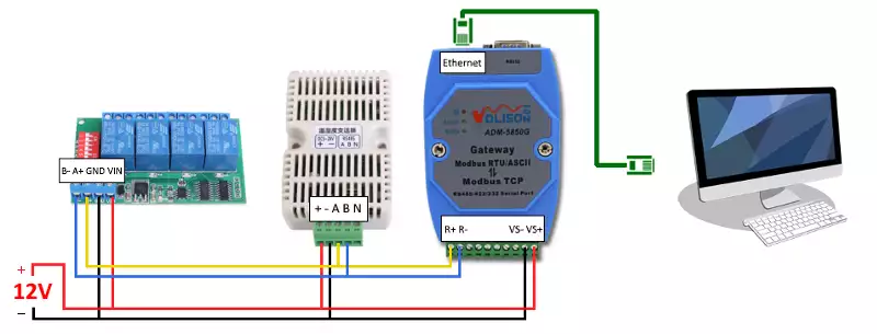
You can connect maximum of 247 slaves (such as relay board, temperature sensor etc.) in parallel to the Modbus RTU/TCP gateway. Each device need to be set the same serial port parameters including baud rate, data bits, stop bits and parity. Furthermore, each device must be have an unique slave ID. The Figure 1 shows how to wire these devices to the gateway. If the devices have not got the same voltage requirements, they must be operated from a separated power supply. Finally, you need an Ethernet cable to connect the Modbus gateway to the PC.
Specifications of Modbus gateway
| Specification | Value |
| Model | ADM-5850G |
| Power supply | DC 9 - 48V |
| Maximum current | 200 mA |
| Communication speed | 300BPS-115.2KBPS |
| Working ways | RTU Master - TCP Slaver TCP Master - RTU Slaver ASCII Master - TCP Slaver TCP Master - ASCII Slaver |
| Supported serial ports | RS232 / RS422 / RS485 |
| Ethernet interface | 10/100M |
Setting up the Modbus RTU/TCP gateway
For successful communication, you need to change the network settings of your computer so that the computer and the Modbus gateway are in a common subnet. The following Table 2 shows an example what should be set when the gateway uses its default settings.
| Computer network settings should be | Gateway default network settings | |
| IP address | 192.168.10.2 | 192.168.10.254 |
| Subnet mask | 255.255.0.0 | 255.255.255.0 |
| Gateway | none | 192.168.10.1 |
| DNS server | none | 0.0.0.0 |
After successful configuration, open your web browser and type the IP address of the Modbus gateway: 192.168.10.254 to the browser URL bar. After the page have loaded, you will see the overview (Figure 3) of the gateway. In this surface, you can configure all the gateway setting including network, serial and modbus settings.

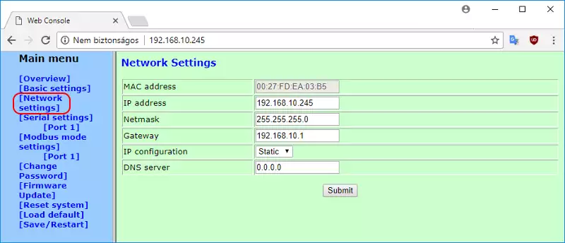
Under network settings (Figure 4), you can customize the Modbus gateway network setting. You can communicate with the gateway using these settings. Only change it if necessary, otherwise leave it in the default settings.
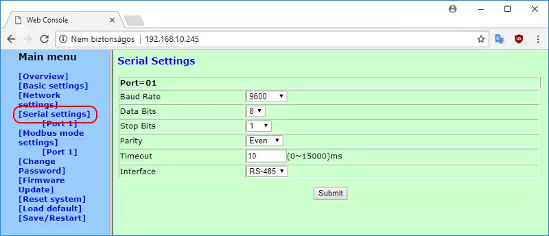
Maximum of 247 devices can be connected in parallel to the Modbus gateway and their serial port settings such as baud rate, data bits and stop bits of these devices need to be match with each other. These settings must be specified for the Modbus gateway under serial setting (Figure 5). The timeout determines every packet by determining the time interval between characters. The interface determines the type of the serial port.
In modbus operating settings shown on Figure 6, the operation mode determines the way of working. In this case (TCP Master - RTU Slaver), the network is the Modbus TCP master device, and the serial port is the Modbus RTU slave device. The connections sets the maximum connection to the Modbus gateway. The default port number of the standard Modbus TCP protocol is 502, but you can also modify it according to your own application. The master device needs a response timeout time when accessing slave device. This time is the message timeout. The ID mapping in auto ID mode, the gateway does not make any change on the request frame. If it changed to fixed, the gateway change the the slave ID of the request Modbus frame to the set value in Fixed ID Value textbox.

For more information about how to set up the gateway, please download the documentation.
Example
Latch channel 1 of a relay board using Modbus TCP
Let's take a 4 channel relay board. After you have connected it the Modbus gateway, attached the gateway to the PC via Ethernet cable and configured it, open the Modbus gateway settings on your web browser. The serial port parameters of this relay board are fixed. So, you need to set these settings (baud rate: 9600, parity: even, data bits: 8, stop bits: 1) in serial settings menu then select the interface as RS-485 and press Submit.
If you would like to latch channel 1 using Modbus RTU, you should send this Modbus RTU message in hex format:| 01 06 00 01 04 00 DA CA |
This Modbus RTU message is equal to the following Modbus TCP message:
| 00 01 00 00 00 06 01 06 00 01 04 00 |
So you need to put the the RTU message into the TCP frame without CRC, like the Figure 7 shows.

Let's see this Modbus TCP/IP message in more detail. The first 2 bytes (0x0001) are the transaction ID that is the identification of the Modbus request/response transaction. The next 2 bytes (0x0000) are the protocol ID. The protocol ID 0 identifies the Modbus protocol. It followed bye 2 bytes (0x0006) that are the message length in byte. Then, there is a unit ID (0x01) that is equal to the slave ID in RTU message. Finally, there are the function code and the data field came from Modbus RTU message. The following Table 3 summarizes these.
| Octet(s) | Description | Format | In this example |
| 00 01 | transaction ID | hex-octet | the ID of this Modbus request is 1 |
| 00 00 | protocol ID | hex-octet | protocol ID 0 identify the Modbus protocol |
| 00 06 | message length | hex-octet | the message is 6 bytes long |
| 01 | unit ID | hex-octet | unit ID equal to the slave ID of the relay board |
| 06 | function code | hex-octet | function code, described in the guide of the relay board |
| 00 01 04 00 | data | hex-octet | data, described in the guide of the relay board |
Buy Modbus RTU/TCP gateway
Connect to Modbus RTU/TCP device from Ozeki Modbus gateway
Step 1 - Create a Modbus TCP connection
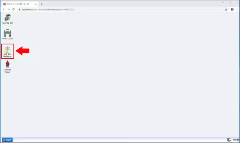
The first step of this guide is to create Modbus TCP connection which makes it possible to communicate the Modbus RTU/TCP device. To do that, the first step is to open Modbus Gateway. For that, open Ozeki 10 GUI by typing 'https://localhost:9515' into your browser. Then, like in Figure 8, open the Modbus Gateway application from the Ozeki 10 desktop.
After you opened the Modbus Gateway application, you will be able to see the main menu of the SMS Gateway. This main menu contains three main sections: Connections, Routes and Users and Applications. Now, at this point, you need to create a connection in Modbus Gateway. To perfrom this operation, just click on 'Add new connection...' as you can see it in Figure 9.

The next menu that shows up, lists all the available connection that can be created in Modbus Gateway. Every option has got a short description that helps you to decide which application is needed in your case. To follow this guide, you just need to have a Modbus TCP connection, so as Figure 10 shows that, just click on the 'Install' button of the connection.

Before finishing the creation of the Modbus TCP connection, you have to specify some details for the connection. This details in this case are th IP address and port for the connection. So, all you need to do is to provide these details for the connection like in Figure 11 and finally, click on Ok to create the connection that needed to complete this guide.

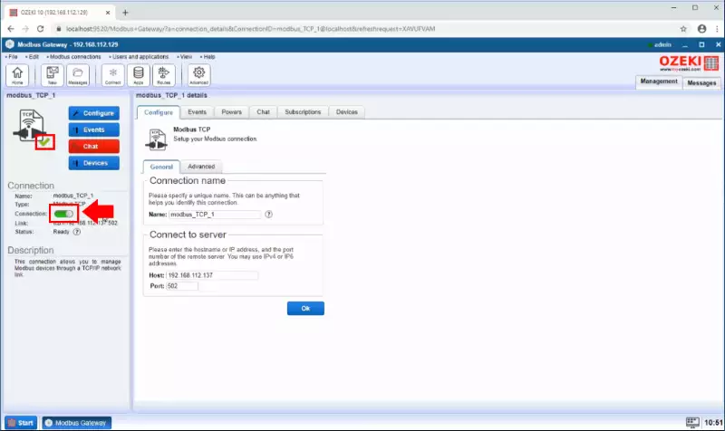
After you created the Modbus TCP connection, the next window is the main menu of the connection. Here, you can modify the details of the connection anytime you want. To connect to the Modbus device, you need to enable the connection here. For that, just click on the toggle as Figure 12 shows. The toggle is green now that indicates that the connection is now active.
Step 2 - Add temperature device to the Modbus connection
To be able to communicate with a temperature Modbus device you need to add it to the Modbus TCP connection. As you can see on the Figure 13 select the Modbus TCP connection Device tab and click on the blue Create new Modbus device button.

Now select the Modbus device connection you wish to install. In this guide we use Tempearure device as you can see on the Figure 14.

In the Modbus device details page as you see on the Figure 15 you need to define the Station ID as Address. This number identifies the device on the Modbus line. Be sure that each device has a unique Station ID.

Step 3 - Communicate with the temperature device
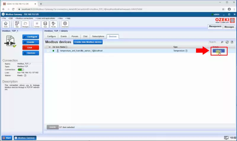
After the device is added, you will see it in the Modbus devcies list. To see the device details and to be able to communicate with it open it's details page by click on the details button at the end of the line like in Figure 16.
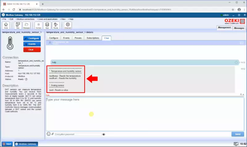
In the device details page Chat tab you are able to communicate with the device by using commands. You can get the available commands by send a "help" message to the device as you can see in the Figure 17.

You will see that the device is send back the available commands. The temperature device commands are "readtemp" , "readhum" and "read".
When you send the apropiate commands the device is send back the informations. As you can see on the Figure 19. If you send the readtemp command to the device it send the courrent temperature in celsius ad if you send the readhum it send the air humidity percentage.

Step 4 - Add relay device to the Modbus connection
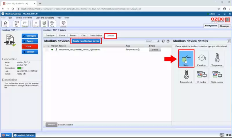
Next add a relay device to the Modbus TCP connection. On the devices tab click on the blue Create new Modbus device button and then select the Relay type connection like in the Figure 20.
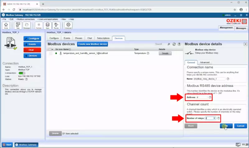
In the Relay Modbus device details page as you see on the Figure 21 you need to define the Station ID as Address and specify the number of relays on the relay board. The Address identifies the device on the Modbus line. Be sure that each device has a unique Station ID.
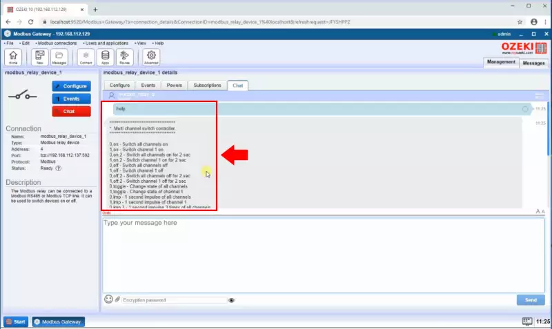
In the device details page Chat tab you are able to communicate with the device by using commands. You can get the available commands by send a "help" message to the device like in the Figure 22. You will see that the relay device is send back the available commands.
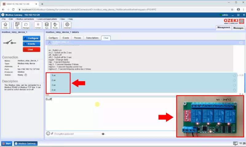
When you send the apropiate commands the device is turn on and off the relays as you can see on the Figure 23.
Modbus Communication log
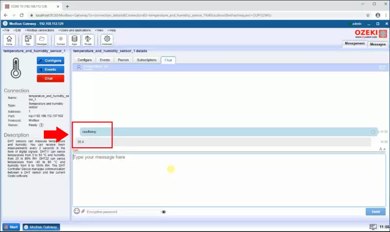
To see a detailed log about the temperature device Modbus communication first send a message to the temperature device and it will send back the apropriate information as you can see in the Figure 24.
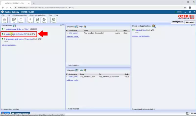
Now open the modbus TCP connection from the Modbus Gateway main page.

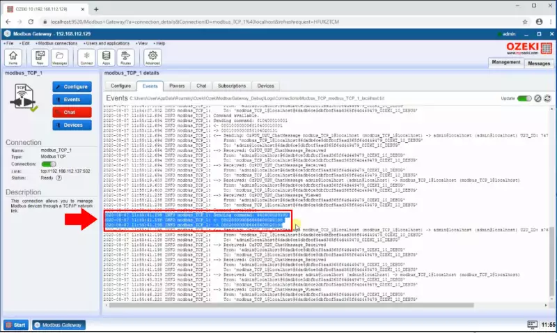
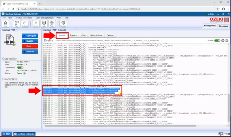
Finally as the Figure 26 shows on the Events tab you will see the detailed Modbus communication.
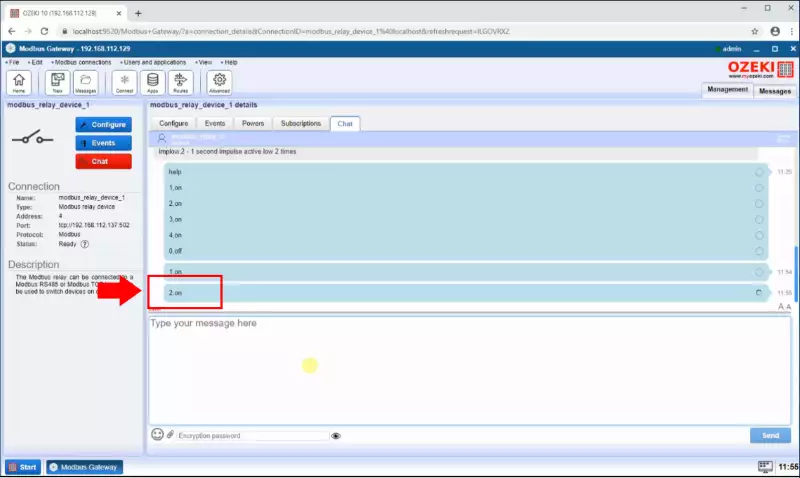
To see a detailed log about the relay device Modbus communication you also need to send message to it like in the Figure 27.
Now open the modbus TCP connection from the Modbus Gateway main page.
Finally as the Figure 29 shows on the Events tab you will see that the Modbus TCP device send the command tu the relay ann it will echo it back.
