Modbus ASCII
When devices are setup to communicate on a MODBUS serial line using ASCII (American Standard Code for Information Interchange) mode, each 8–bit byte in a message is sent as two ASCII 4 bit characters. This mode is used when the physical communication link or the capabilities of the device does not allow the conformance with RTU timer management requirements.
This mode is less efficient than RTU since each byte needs two characters. Example : The byte 0x7D is encoded as two characters : 0x35 and 0x42 (0x37 = '7', and 0x44 = 'D' in ASCII Table).
MODBUS frame description
The MODBUS application protocol defines a simple Protocol Data Unit (PDU) independent of the underlying communication layers.

The mapping of MODBUS protocol on a specific bus or network introduces some additional fields on the Protocol Data Unit. The client that initiates a MODBUS transaction builds the MODBUS PDU, and then adds fields in order to build the appropriate communication PDU.

The valid slave nodes addresses are in the range of 0 – 247 decimal. The individual slave devices are assigned addresses in the range of 1 – 247. A master addresses a slave by placing the slave address in the address field of the message. When the slave returns its response, it places its own address in the response address field to let the master know which slave is responding. On MODBUS Serial Line, the Address field only contains the slave address.
The function code indicates to the server what kind of action to perform. The function code can be followed by a data field that contains request and response parameters.
Error checking field is the result of a Redundancy Checking calculation that is performed on the message contents. Two kinds of calculation methods are used depending on the transmission mode that is being used (RTU or ASCII).
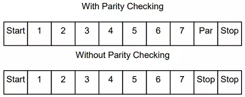
The format (10 bits) for each byte in ASCII mode
| Coding System: | Hexadecimal, ASCII characters 0–9, A–F One hexadecimal character contains 4-bits of data within each ASCII character of the message |
| Bits per Byte: | 1 start bit |
| 7 data bits, least significant bit sent first | |
| 1 bit for even/odd parity, no bit for no parity | |
| 1 stop bit if parity is used, 2 bits if no parity |
Even parity is required, other modes (odd parity, no parity) may also be used. In order to ensure a maximum compatibility with other products, it is recommended to support also No parity mode. The default parity mode must be Even parity.
How characters are transmitted serially
Each character or byte is sent in this order (left to right): Least Significant Bit (LSB) . . . Most Significant Bit (MSB)

MODBUS Message ASCII framing
A MODBUS message is placed by the transmitting device into a frame that has a known beginning and ending point. This allows devices that receive a new frame to begin at the start of the message, and to know when the message is completed. Partial messages must be detected and errors must be set as a result. The address field of a message frame contains two characters. In ASCII mode, a message is delimited by specific characters as Start-of-frames and End-of-frames. A message must start with a ‘colon’ (:) character (ASCII 0x3A), and end with a ‘carriage return – line feed’ (CRLF) pair (in ASCII 0x0D and 0x0A). The allowable characters transmitted for all other fields are hexadecimal 0–9, A–F (ASCII coded). The devices monitor the bus continuously for the ‘:’ character. When this character is received, each device decodes the next character until it detects the (EOF) End-Of-Frame. Intervals of up to one second may elapse between characters within the message. Unless the user has configured a longer timeout, an interval greater than 1 second means an error has occurred. Some Wide-Area-Network application may require a timeout in the 4 to 5 second range.

The maximum size of a MODBUS ASCII frame is 513 bytes.
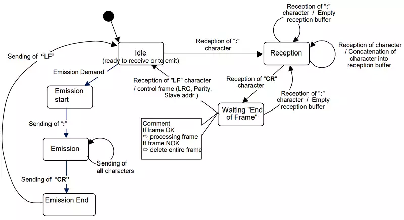
The ASCII framing requirements are synthesized in the following state diagram. Both 'master' and 'slave' points of view are expressed in the same drawing.

Some explanations about the above state diagram:
- 'Idle' state is the normal state when neither emission nor reception is active.
- 'Idle' state is the normal state when neither emission nor reception is active.
- Each reception of a ':' character means a beginning of a new message. If a message was in process of reception while receiving such a character, the current message is declared incomplete and it is discarded. A new reception buffer is then allocated.
- After detection of the end of frame, the LRC calculation and checking is completed. Afterwards the address field is analyzed to determine if the frame is for the device. If not the frame is discarded. In order to reduce the reception processing time the address field can be analyzed as soon as it is reserved without waiting the end of frame.
Parity checking
Users may configure devices for Even (required) or Odd Parity checking, or for No Parity checking (recommended). This will determine how the parity bit will be set in each character. If either Even or Odd Parity is specified, the quantity of 1 bits will be counted in the data portion of each character (7 data bits for ASCII mode, or 8 for RTU). The parity bit will then be set to a 0 or 1 to result in an Even or Odd total of 1 bits. For example, these 8 data bits are contained in an RTU character frame: 0110101 The total quantity of 1 bits in the frame is four. If Even Parity is used, the frame’s parity bit will be a 0, making the total quantity of 1 bits still an even number (four).If Odd Parity is used, the parity bit will be a 1, making an odd quantity (five). When the message is transmitted, the parity bit is calculated and applied to the frame of each character. The device that receives counts the quantity of 1 bits and sets an error if they are not the same as configured for that device (all devices on the MODBUS Serial Line must be configured to use the same parity checking method). Note that parity checking can only detect an error if an odd number of bits are picked up or dropped in a character frame during transmission. For example, if Odd Parity checking is employed, and two 1 bits are dropped from a character containing three 1 bits, the result is still an odd count of 1 bits. If No Parity checking is specified, no parity bit is transmitted and no parity checking can be made. An additional stop bit is transmitted to fill out the character frame.
Frame checking field: Longitudinal Redundancy Checking (LRC)
In ASCII mode, messages include an error–checking field that is based on a Longitudinal Redundancy Checking (LRC) calculation that is performed on the message contents, exclusive of the beginning ‘colon’ and terminating CRLF pair characters. It is applied regardless of any parity checking method used for the individual characters of the message. The LRC field is one byte, containing an 8–bit binary value. The LRC value is calculated by the device that emits, which appends the LRC to the message. The device that receives calculates an LRC during receipt of the message, and compares the calculated value to the actual value it received in the LRC field. If the two values are not equal, an error results. The LRC is calculated by adding together successive 8–bit bytes of the message, discarding any carries, and then two’s complementing the result. It is performed on the bytes of the message, before the encoding of each byte in the two ASCII characters corresponding to the hexadecimal representation of each nibble. The computation does not include the 'colon' character that begins the message, and does not include the CRLF pair at the end of the message. The resulting LRC is ASCII encoded into two bytes and placed at the end of the ASCII mode frame before the CRLF.
Error checking methods
The security of standard MODBUS Serial Line is based on two kinds of error checking:
- Parity checking (even or odd) should be applied to each character.
- Frame checking (LRC for ASCII frames or CRC for RTU frames) must be applied to the entire message.
Both the character checking and message frame checking are generated in the device (master or slave) that emits and applied to the message contents before transmission. The device (slave or master) checks each character and the entire message frame during receipt.
The master is configured by the user to wait for a predetermined timeout interval ( Response time-out) before aborting the transaction. This interval is set to be long enough for any slave to respond normally ( unicast request). If the slave detects a transmission error, the message will not be acted upon. The slave will not construct a response to the master. Thus the timeout will expire and allow the master’s program to handle the error. Note that a message addressed to a nonexistent slave device will also cause a timeout.
Example Modbus ASCII frame
Here is an example of a Modbus ASCII request for the content of analog output holding registers #40108 to #40110 from the slave device with address 21. : 1 5 0 3 0 0 6 B 0 0 0 3 7 A CR LF 1 5: The SlaveID Address (21 = 0x15 = '0' and '5') 0 3: The function code (read analog output holding registers) 0 0 6 B: The data address of the first register requested. (40108 - 40001 offset = 107 = 0x6B) 0 0 0 3: The total number of registers requested. (read 3 registers 40108 to 40110) 7 A: The LRC (Longitudinal redundancy check) for error checking.
Contents retrieved from
- http://www.modbus.org/
