Ozeki Audio Module
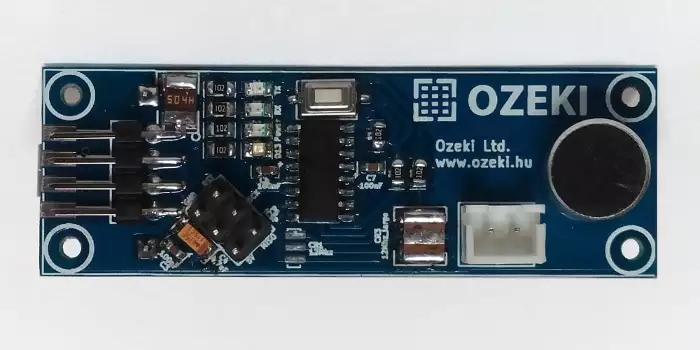
The Ozeki Audio Module is a modified Arduino Nano, that was built to capture sound with microphone. This is an open source board, with all the files needed for manufacturing. You may also freely modify the design.
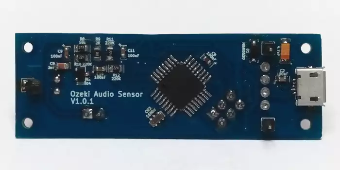
The contains an ATmega328P microcontroller so you can program it just like an Arduino Nano using the Arduino IDE environment. It has a micro USB port, which is compatible with mobile phone USB cables. It is better then using an Arduino Nano, because it is more compact solution, since the microphone is soldered directly to the board.


|
Download files for manufacturing
|
|
Datasheets
Tutorials
Examples
|
Specifications:
- IC: ATmega328P
- Clock Speed: 16 MHz
- Flash Memory: 32 KB
- SRAM: 2 KB
- EEPROM: 1 KB
- USB support provided by a CH340G USB to serial chip:
- Micro USB (compatible with mobile phone USB cables)
- Connection to the Ozeki HUB Controller
- Power supply from USB (5V)
- 500mA resettable fuse
- Status LEDs: power, TX, RX, D13
- Can be screwed on an Ozeki Matrix Board
- Product dimensions:
2.40in.[60.96mm]×0.80in.[20.32mm] - The provided microphone by Ozeki:
- Frequency response from 500 Hz to 6000 Hz
(After digitalisation.) - Listener pin (the electret microphone): A5
- Frequency response from 500 Hz to 6000 Hz
- You can connect the microphone to it or solder it to the module.
- Only supports electret microphones.
Pinout of the :

Program codes
This code checks the intensity of the sound
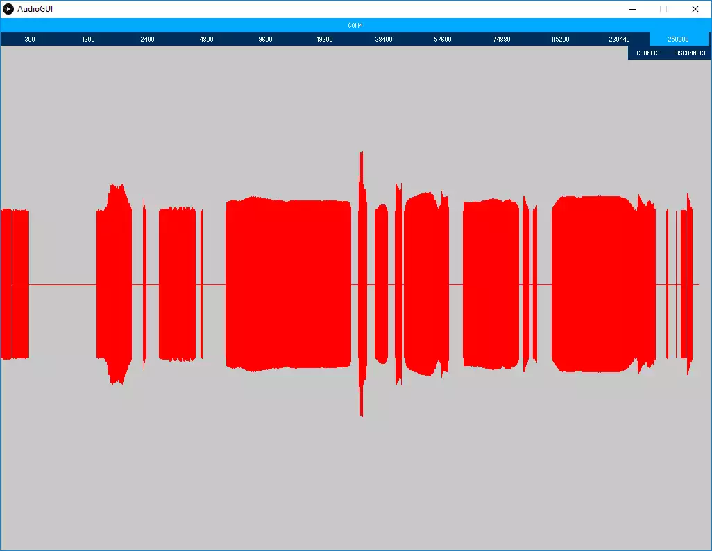
It listens to the integrated microphone of the . Checks the intensity of the sound and writes it on the serial. Every time it detects a bigger intensity then 140, the default led on pin 13 will light up. It can send the sound intensity information to the GUI which is designed to graphically show it.
To connect the to the GUI please download the code (.zip) and follow these steps:
- Step 1: Upload the example code to your
- Step 2: Download Processing: https://processing.org/
- Step 3: Start AudioGUI.pde with processing.exe
- Step 4: In the GUI select the COM port of the module and the baud rate (our example is set to 250000).
Downloadable code:
Video 1 - How to measure sound intensity by using an electret microphone
Example code+GUI (.zip) Source Code 1 - Arduino example for converting audio input voltage to integer. It uses the A/D converter.
volatile int value = 0;

ISR(ADC_vect){ 	//INTERRUPT activated when a selected ADC value has changed
				//in this code ADC5 is selected in the ADMUX register

  value = ADCH; //the first 8 bits of the 10 bit ADC value
  				//the reamaining 2 bits are in ADCL
  				// This is in the range of an electret microphone.
  				// By default, the result is presented right adjusted,
  				// but it can optionally be presented left adjusted
  				// by setting the ADLAR bit in ADMUX.

  ADCSRA|= _BV(ADSC); //sets ADSC bit to 1 to start each conversion
  					  //ADSC resets to 0 after every conversion
}

void checkValue(){
  if ( value > 140){
      	Serial.println(value); //the AD converted result of the microphone voltage
        digitalWrite(13,HIGH);
        delay(10);
    }
    else {
      Serial.println(0);
      digitalWrite(13,LOW);
    }
  }

void setup() {
  Serial.begin(250000);
  pinMode(A5, INPUT);
  pinMode(13, OUTPUT);

  //ADMUX is the ADC Multiplexer Selection Register
  ADMUX|= _BV(REFS0)|_BV(ADLAR)|_BV(MUX2)|_BV(MUX0);
  		//REFS0 are set to 1 to set ref voltage to AVCC
  				//with external capacitor at AREF pin
  		//ADLAR is set to 1 to present the ADCH bits left adjusted
  		//MUX2 and MUX0 are set to 1 to set the input to ADC5

  //ADCSRA is the ADC Control and Status Register A
  ADCSRA|= _BV(ADEN)|_BV(ADIE)|_BV(ADPS1)|_BV(ADPS0);
  		//ADEN set to 1 enables the ADConverter (ADC)
  		//ADIE set to 1 activates the ADC Conversion Complete Interrupt
  		//ADPS1 and ADPS0 are set to 1 to set the division factor to 8
  		//between the XTAL frequency and the input clock to the ADC.
  ADCSRA|= _BV(ADSC); //sets ADSC bit to 1 to start each conversion
}

void loop() {
  checkValue();
}
