Which breadboards to use for a given project
Contents
- Using a breadboard
- Using a prototyping PCB board
- Use shield boards
- Building your own circuit
- How to embed the atmega 328 microcontroller on your board
- References
Using a breadboard
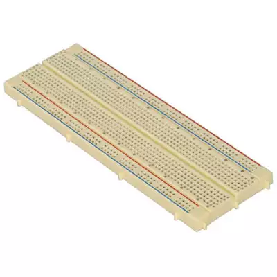
There are many reasons to build your own Arduino circuit on a breadboard. It takes less space, projects do not always require every pin to be used on the I/O headers, or maybe you will not be using a shield, but you still want Arduino as the brain of your project.

Breadboard
Using a prototyping PCB board
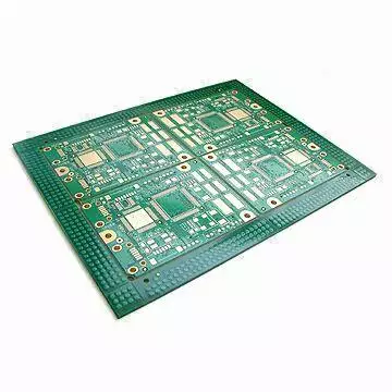
A printed circuit board (PCB) mechanically supports and electrically connects electronic components using conductive tracks, pads and other features etched from copper sheets laminated onto a non-conductive substrate. PCBs can be single sided (one copper layer), double sided (two copper layers) or multi-layer. Conductors on different layers are connected with plated-through holes called vias. Advanced PCBs may contain components - capacitors, resistors or active devices - embedded in the substrate.

Printed circuit board
Use shield boards
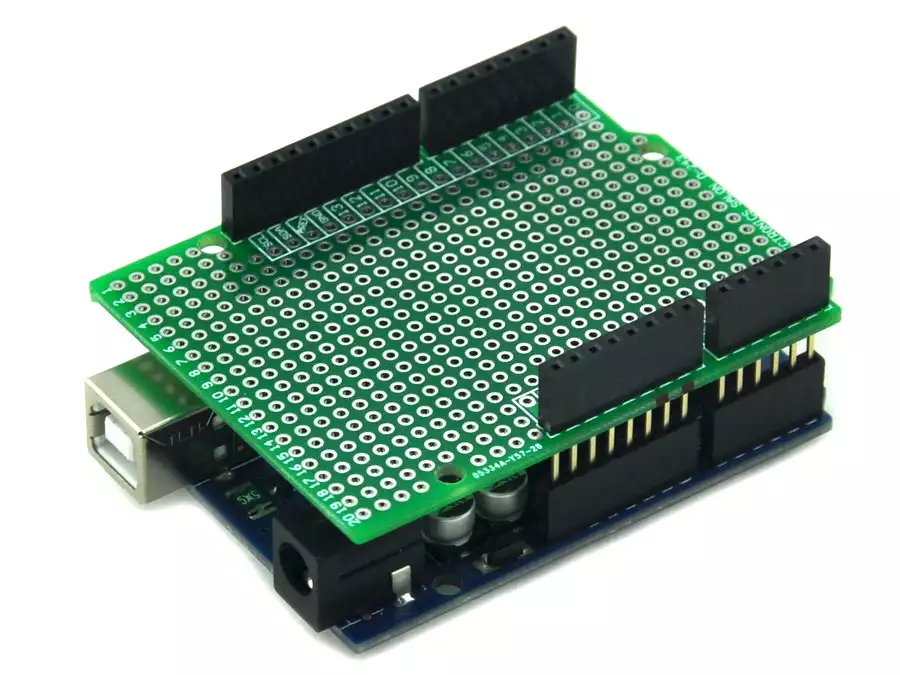
Shield boards are excellent options for building small circuits that act as an arduino shield without the pain of designing a PCB. Shield boards are prototype PCB-s designed to fit on an Arduino. On typical shield boards all holes are plated through, top and bottom side are identical copper layers. Pads grid (pitch) is 2.54mm / 0.1″ and hole diameter 0.9m allowing most parts to fit in. An example shield board can be seen on the following pictures:
Arduino UNO R3 Shield Board

Arduino UNO R3 Shield Board
Building your own circuit
To create your first circuit you will need a toolkit with the following things:
- 1x Arduino board
- 1x LED
- 1x 330 ohm resistor
Arduino circuit
Method:
- With a wire, connect ground from the Arduino (labeled GND) to the bottom row of the farthest right column of the bread board.
- With a wire, connect power from where it says 5V (the V stands for voltage and this is where the electric power comes from.) on the Arduino to the bottom row of the next to right column.
- Connect the resistor with one end in h2 and the other end on the far right column (ground).
- Connect the LED cathode (shorter leg) to f2. (This makes it connect to the resistor through the breadboard because they are on the same row.)
- Connect the LED anode (longer leg) to f3.
- Connect a wire from h3 to the next to right column (+5V).
- Plug power into the Arduino .
- The LED should light up. If it doesn’t, unplug power from the Arduino,check all of your connections and make sure you have not plugged the LED in backwards. Then try power again.
How to embed the atmega 328 microcontroller on your board
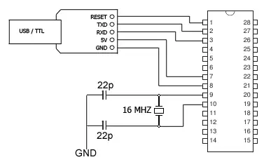
Once your Arduino prototype is working, you might want to user the ATmega328P microcontroller directly on your board. To do this it is best to start with an ATmega328P microcontroller that comes pre-loaded with the Arduino UNO (16MHz) Bootloader. You will also need a 16Mhz crystal, and one 28 pin Dil Socket as well as 2 x 22pf load capacitors. This will allow you to use Arduino code in your custom embedded project without having to use an actual Arduino board.
To get this chip working with Arduino IDE, you will need the 16Mhz crystal, and an external 5V supply, or you could use a usb to ttl converter to power the chip and upload your sketches (pictured below) just like you do with your arduino.
Atmel’s ATMega328 8-Bit Processor in 28 pin DIP package. It’s like the ATmega168, with double the flash space. 32K of program space. 23 I/O lines, 6 of which are channels for the 10-bit ADC. Runs up to 20MHz with external crystal. Package can be programmed in circuit. 1.8V to 5V operating voltage! Note: This contains the bootloader used on the Arduino UNO.
If you cannot get an ATMega328 preloaded with the Arduino UNO (16MHz) Bootloader, you can use a working Arduino Uno to burn the bootloader yourself.

