Connect Arduino to the Mobile Network
Contents
- Introduction
- Specification
- Connecting the Shield
- GSM Library
- Begin sending SMS
- How to send SMS message with GSM Shield
- How to read SMS messages with GSM Shield
- Video Guide
- References
Introduction
In a DIY world Arduino is one of the best hardwares for making computers that can sense and control more of the physical world than your desktop computer. It’s an open-source physical computing platform based on a simple microcontroller board, and a development environment for writing software for the board.There are plenty of boards, shields, accessories for the Arduino in order to help you achive your ideals.
With the Arduino GSM Shield you can connect to the Internet or you can send / receive SMS messages using the Arduino board. To send / receive SMS you have to connect your device to a GSM network. For this solution, you need a subscription with a mobile phone operator and a Subscriber Identity Module (SIM) card. The network operator provides the SIM card, which contains information such as the mobile number, and can store limited amounts of contacts and SMS messages.
To use GPRS for Internet access, and for the Arduino to request or serve webpages, you need to obtain the Access Point Name (APN) and a username/password from the network operator.
Specification
1. SIM900 GSM/GPRS Shield:
The hardware is a GSM/GPRS shield for Arduino based on the SIM900 Quad-band GSM/GPRS module. It is controlled via AT commands (GSM 07.07 ,07.05 and SIMCOM enhanced AT Commands), and fully compatible with Arduino / Iteaduino and Mega.
Features:
- Quad-Band 850/900/1800/1900MHz
- GPRS mobile station class B
- GPRS multi-slot calss 10/8
- GPRS mobile station class B
- Compliant to GSM phase 2/2+
- Class 4 (2W@850/900MHz)
- Class 1 (1W@1800/1900MHz)
- Control via commands (GSM 07.07, 07.05 and SIMCOM enhanced AT Commands)
- Short message service
- Free serial port selection
- All SIM900 pins breakout
- RTC supported with SuperCap
- Operation temperature: -40℃ ~ +85℃
Specifications:
| PCB size | 71.4mm X 66.0mm X 1.6mm |
| Indicators | PWR, status LED, net status LED |
| Power supply | 9~20V, compatible with Arduino |
| Communication Protocol | UART |
| RoSH | Yes |
Electrical Characteristics:
| Specification | Min | Type | Max | Unit |
|---|---|---|---|---|
| Power Voltage(Vlogic) | 4.5 | 5 | 5.5 | VDC |
| Power Voltage(Vsupply) | 9 | - | 20 | VDC |
| Input Voltage VH: | 4.5 | 5 | 5.5 | V |
| Input Voltage VL: | -0.3 | 0 | 0.5 | V |
| Current Consumption(pulse) | - | - | 2000 | mA |
| Current Consumption(Continues) | 500 | mA | ||
| Baud rate | 9600 | bps | ||

2. Mega2560 board:
| Microcontroller | ATmega2560 |
| Input Voltage (limits) | 6-20V |
| Digital I/O Pins | 54 (of which 14 provide PWM output) |
| Analog Input Pins | 16 |
| DC Current per I/O Pin | 40 mA |
| DC Current for 3.3V Pin | 50 mA |
| Flash Memory | 256 KB of which 8 KB used by bootloader |
| SRAM | 8 KB |
| EEPROM | 4 KB |
| Clock Speed | 16 MHz |
Connecting the Shield
Connecting the Shield to Arduino UNO
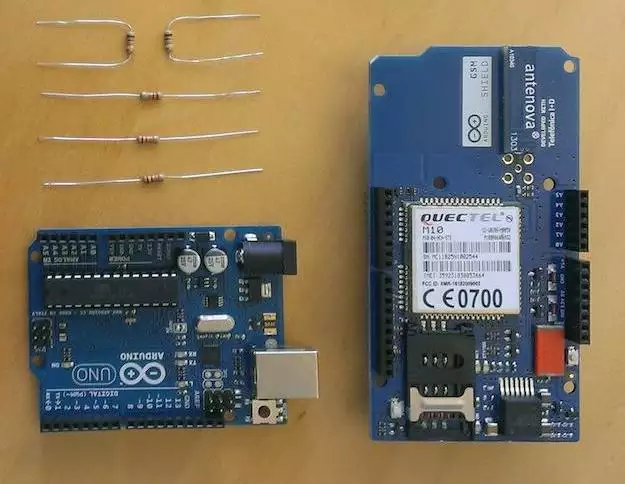
To use the shield, you’ll need to insert a SIM card into the holder. Insert the SIM in the plastic holder so that the metal contacts are facing the shield, with the notch of the card at the top of the bracket. Once the SIM is inserted, mount it on top of an Arduino board.
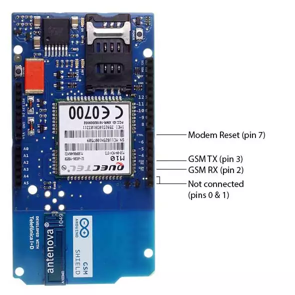
Digital pins 2, 3 and 7 are reserved for communication between the Arduino and modem and cannot be used by your sketches. Communication between the modem and Arduino is handled by the Software Serial library on pins 2 and 3. Pin 7 is used for the modem reset.

Connecting the Shield to Arduino Leonardo
The GSM Library uses digital pin 8 to communicate with Leonardo. On the GSM shield, connect a jumper wire between digital pins 2 and 8.
Connectin the Shield to Arduino Mega
The GSM Library uses digital pin 10 to communicate with Mega. On the GSM shield, connect a jumper wire between digital pins 2 and 10.
Bend the male header attached to pin 2 on the GSM shield to the side so it does not connect to Mega.
How to upload skeches
To upload sketches to the board, connect your Arduino to your computer with a USB cable and upload your sketch with the Arduino IDE. Once the sketch has been uploaded, you can disconnect the board from your computer and power it with an external power supply.
When the yellow status LED turns on, it means the modem is powered, and you can try connecting to the network.
Developer versions of the GSM shield required you to press press the Power button on the shield for a few moments to turn the modem on. If you have an early version of the shield, and it does not turn on automatically, you can solder a jumper to the CTRL/D7 pad on the reverse side of the board, and it will turn on when an attached Arduino receives power.
The shield should work in any area with GSM coverage. Before buying the shield please verify that this kind of coverage is available where you plan to use it.
GSM Library
The GSM library handles communication between Arduino and the GSM shield. The majority of functions are for managing data, voice, and SMS communication. There are also a number of utilities for managing information about the modem and the SIM card’s PIN.
Testing the modem and network connection
This sketch will check the modem’s IMEI number. This number is unique to each modem, and is used to identify valid devices that can connect to a GSM network. Once the number has been read from the modem, the Arduino will print out the network carrier it is connected to, and the signal strength of the network over the serial port.
// import the GSM library
#include <GSM.h>

// PIN Number
#define PINNUMBER “”

// initialize the library instance
GSM gsmAccess(true);     // include a ‘true’ parameter for debug enabled
GSMScanner scannerNetworks;
GSMModem modemTest;

// Save data variables
String IMEI = “”;

// serial monitor result messages
String errortext = “ERROR”;

void setup()
{
// initialize serial communications
Serial.begin(9600);
Serial.println(“GSM networks scanner”);
scannerNetworks.begin();

// connection state
boolean notConnected = true;

// Start GSM shield
// If your SIM has PIN, pass it as a parameter of begin() in quotes
while(notConnected)
{
if(gsmAccess.begin(PINNUMBER)==GSM_READY)
notConnected = false;
else
{
Serial.println(“Not connected”);
delay(1000);
}
}

// get modem parameters
// IMEI, modem unique identifier
Serial.print(“Modem IMEI: “);
IMEI = modemTest.getIMEI();
IMEI.replace(“\n”,””);
if(IMEI != NULL)
Serial.println(IMEI);

// currently connected carrier
Serial.print(“Current carrier: “);
Serial.println(scannerNetworks.getCurrentCarrier());

// returns strength and ber
// signal strength in 0-31 scale. 31 means power > 51dBm
// BER is the Bit Error Rate. 0-7 scale. 99=not detectable
Serial.print(“Signal Strength: “);
Serial.print(scannerNetworks.getSignalStrength());
Serial.println(” [0-31]“);
}

void loop()
{
// scan for existing networks, displays a list of networks
Serial.println(“Scanning available networks. May take some seconds.”);

Serial.println(scannerNetworks.readNetworks());

// currently connected carrier
Serial.print(“Current carrier: “);
Serial.println(scannerNetworks.getCurrentCarrier());

// returns strength and ber
// signal strength in 0-31 scale. 31 means power > 51dBm
// BER is the Bit Error Rate. 0-7 scale. 99=not detectable
Serial.print(“Signal Strength: “);
Serial.print(scannerNetworks.getSignalStrength());
Serial.println(” [0-31]“);

}
Begin sending SMS
First of all you have to identify the telephone number where you wish to send an SMS message. In this section you have to add the data of the recipient.
Syntax
SMS.beginSMS(number)
Parameters
number : char array, the phone number to send the SMS to
Returns
int
In asynchronous mode, beginSMS() returns 0 if the last command is still executing, 1 if success, and >1 if there is an error. In synchronous mode, it returns 1 if it successfully executes, and 0 if it does not.
Example
#include <GSM.h>

#define PINNUMBER “”

// initialize the library instance
GSM gsmAccess; // include a ‘true’ parameter for debug enabled
GSM_SMS sms;

void setup()
{
// initialize serial communications
Serial.begin(9600);

Serial.println(“SMS Messages Sender”);

// connection state
boolean notConnected = true;

// Start GSM shield
// If your SIM has PIN, pass it as a parameter of begin() in quotes
while(notConnected)
{
if(gsmAccess.begin(PINNUMBER)==GSM_READY)
notConnected = false;
else
{
Serial.println(“Not connected”);
delay(1000);
}
}

Serial.println(“GSM initialized”);
}

void loop()
{

Serial.print(“Enter a mobile number: “);
char remoteNumber[20];  // telephone number to send sms
readSerial(remoteNumber);
Serial.println(remoteNumber);

// sms text
Serial.print(“Now, enter SMS content: “);
char txtMsg[200];
readSerial(txtMsg);
Serial.println(“SENDING”);
Serial.println();
Serial.println(“Message:”);
Serial.println(txtMsg);

// send the message
sms.beginSMS(remoteNumber);
sms.print(txtMsg);
sms.endSMS();
Serial.println(“\nCOMPLETE!\n”);
}

/*
Read input serial
*/
int readSerial(char result[])
{
int i = 0;
while(1)
{
while (Serial.available() > 0)
{
char inChar = Serial.read();
if (inChar == ‘\n’)
{
result[i] = ‘\0′;
Serial.flush();
return 0;
}
if(inChar!=’\r’)
{
result[i] = inChar;
i++;
}
}
}
}
How to send SMS message with GSM Shield
Once you have connected to your network with the sketch above, you can test some of the other functionalities of the board. This sketch will connect to a GSM network and send an SMS message to a phone number of your choice.
#include <GSM.h>

#define PINNUMBER “”

// initialize the library instance
GSM gsmAccess; // include a ‘true’ parameter for debug enabled
GSM_SMS sms;

// char array of the telephone number to send SMS
// change the number 1-212-555-1212 to a number
// you have access to
char remoteNumber[20]= “12125551212″;

// char array of the message
char txtMsg[200]=”Test”;

void setup()
{
// initialize serial communications
Serial.begin(9600);

Serial.println(“SMS Messages Sender”);

// connection state
boolean notConnected = true;

// Start GSM shield
// If your SIM has PIN, pass it as a parameter of begin() in quotes
while(notConnected)
{
if(gsmAccess.begin(PINNUMBER)==GSM_READY)
notConnected = false;
else
{
Serial.println(“Not connected”);
delay(1000);
}
}
Serial.println(“GSM initialized”);
sendSMS();
}

void loop()
{
// nothing to see here
}

void sendSMS(){

Serial.print(“Message to mobile number: “);
Serial.println(remoteNumber);

// sms text
Serial.println(“SENDING”);
Serial.println();
Serial.println(“Message:”);
Serial.println(txtMsg);

// send the message
sms.beginSMS(remoteNumber);
sms.print(txtMsg);
sms.endSMS();
Serial.println(“\nCOMPLETE!\n”);
}
How to read SMS messages with GSM Shield
Description
Reads a byte from an SMS message. read() inherits from the Stream utility class.
Syntax
SMS.read()
Parameters
none
Returns
int – the first byte of incoming serial data available (or -1 if no data is available)
Example
#include <GSM.h>

// PIN Number
#define PINNUMBER “”

// initialize the library instance
GSM gsmAccess; // include a ‘true’ parameter for debug enabled
GSM_SMS sms;

char remoteNumber[20];  // Holds the emitting number

void setup()
{
// initialize serial communications
Serial.begin(9600);

Serial.println(“SMS Messages Receiver”);

// connection state
boolean notConnected = true;

// Start GSM shield
// If your SIM has PIN, pass it as a parameter of begin() in quotes
while(notConnected)
{
if(gsmAccess.begin(PINNUMBER)==GSM_READY)
notConnected = false;
else
{
Serial.println(“Not connected”);
delay(1000);
}
}

Serial.println(“GSM initialized”);
Serial.println(“Waiting for messages”);
}

void loop()
{
char c;

// If there are any SMSs available()
if (sms.available())
{
Serial.println(“Message received from:”);

// Get remote number
sms.remoteNumber(remoteNumber, 20);
Serial.println(remoteNumber);

// This is just an example of message disposal
// Messages starting with # should be discarded
if(sms.peek()==’#’)
{
Serial.println(“Discarded SMS”);
sms.flush();
}

// Read message bytes and print them
while(c=sms.read())
Serial.print(c);

Serial.println(“\nEND OF MESSAGE”);

// delete message from modem memory
sms.flush();
Serial.println(“MESSAGE DELETED”);
}

delay(1000);

}
Video Guide
https://www.youtube.com/watch?v=PMOZQgi7K14
References
- http://arduino.cc/en/Main/ArduinoGSMShield
- http://arduino-info.wikispaces.com/GSM-GPRS
- http://arduino.cc/en/Tutorial/GSMExamplesReceiveSMS
- http://www.instructables.com/id/Arduino-GSM-shield/
- http://arduino.cc/en/Tutorial/GSMExamplesSendSMS
- http://wiki.seeedstudio.com/GPRS_Shield_v1.0/
- http://comoyo.github.io/blog/2013/08/01/m2m_adventures
